
the black pyramid but there was no statue on top, just a anode / dielectric antenna.
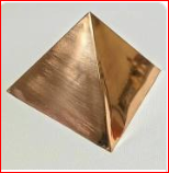
copper pyramidian
Anode
Description An anode is an electrode through which the conventional current enters into a polarized electrical device. This contrasts with a cathode, an electrode through which conventional current leaves an electrical device. A common mnemonic is ACID, for "anode current into device"
An anode is an electrode through which the conventional current enters into a polarized electrical device. This contrasts with a cathode, an electrode through which conventional current leaves an electrical device. A common mnemonic is ACID, for "anode current into device".[1] The direction of conventional current (the flow of positive charges) in a circuit is opposite to the direction of electron flow, so (negatively charged) electrons flow out the anode into the outside circuit. In a galvanic cell, the anode is the electrode at which the oxidation reaction occurs.
An anode is also the wire or plate having excess positive charge.[2] Consequently, anions will tend to move towards the anode. Historically, the anode has also been known as the zincode.
Contents
1Charge flow
2Examples
3Etymology
4Electrolytic anode
5Battery or galvanic cell anode
6Vacuum tube anode
7Diode anode
8Sacrificial anode
9Related antonym
10See also
11References
12External links
dielectric antenna
A dielectric resonator antenna (DRA) is a radio antenna mostly used at microwave frequencies and higher, that consists of a block of ceramic material of various shapes, the dielectric resonator, mounted on a metal surface, a ground plane. Radio waves are introduced into the inside of the resonator material from the transmitter circuit and bounce back and forth between the resonator walls, forming standing waves. The walls of the resonator are partially transparent to radio waves, allowing the radio power to radiate into space.[1]
An advantage of dielectric resonator antennas is they lack metal parts, which become lossy at high frequencies, dissipating energy. So these antennas can have lower losses and be more efficient than metal antennas at high microwave and millimeter wave frequencies.[1] Dielectric waveguide antennas are used in some compact portable wireless devices, and military millimeter-wave radar equipment. The antenna was first proposed by Robert Richtmyer in 1939.[2] In 1982, Long et al. did the first design and test of dielectric resonator antennas considering a leaky waveguide model assuming magnetic conductor model of the dielectric surface .[3]
An antenna like effect is achieved by periodic swing of electrons from its capacitive element to the ground plane which behaves like an inductor. The authors further argued that the operation of a dielectric antenna resembles the antenna conceived by Marconi, the only difference is that inductive element is replaced by the dielectric material.[4]
Contents
1Features
2See also
3References
4External links
5Notes
electrode potential relative to the electrolyte solution being different for the anode and cathode metal/electrolyte systems); but, external to the cell in the circuit,
